scico.linop.xray
X-ray transform classes.
The tomographic projections that are frequently referred to as Radon transforms are referred to as X-ray transforms in SCICO. While the Radon transform is far more well-known than the X-ray transform, which is the same as the Radon transform for projections in two dimensions, these two transform differ in higher numbers of dimensions, and it is the X-ray transform that is the appropriate mathematical model for beam attenuation based imaging in three or more dimensions.
SCICO includes its own integrated 2D and 3D X-ray transforms, and also provides interfaces to those implemented in the ASTRA toolbox and the svmbir package.
2D Transforms
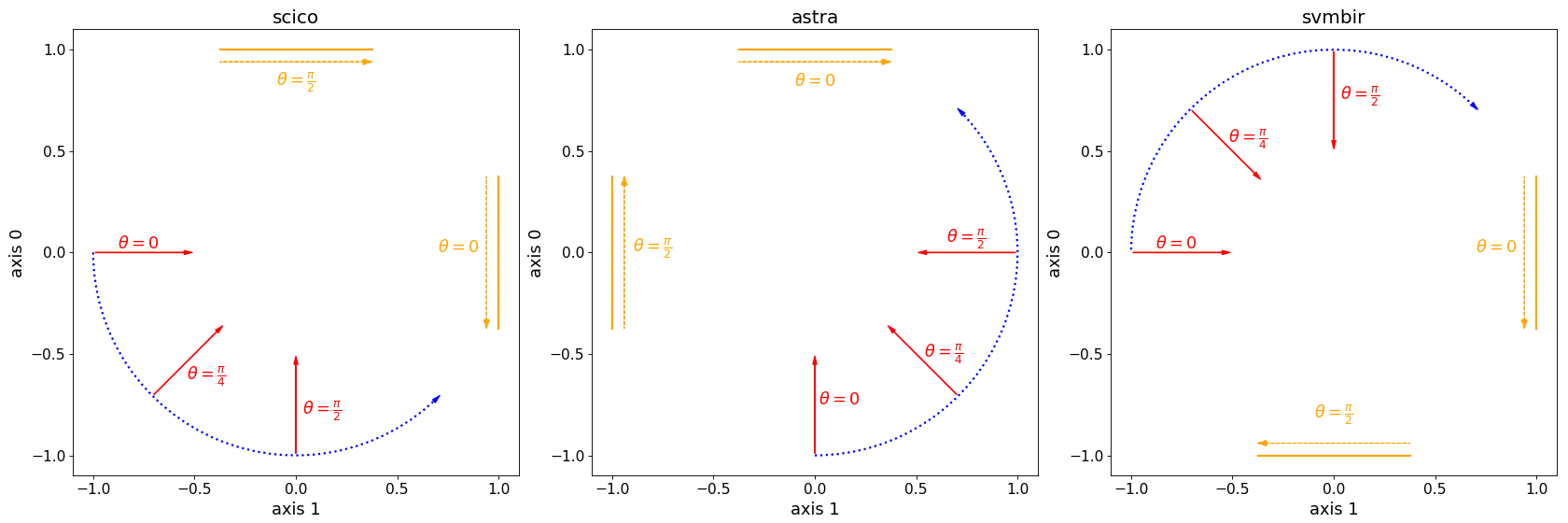
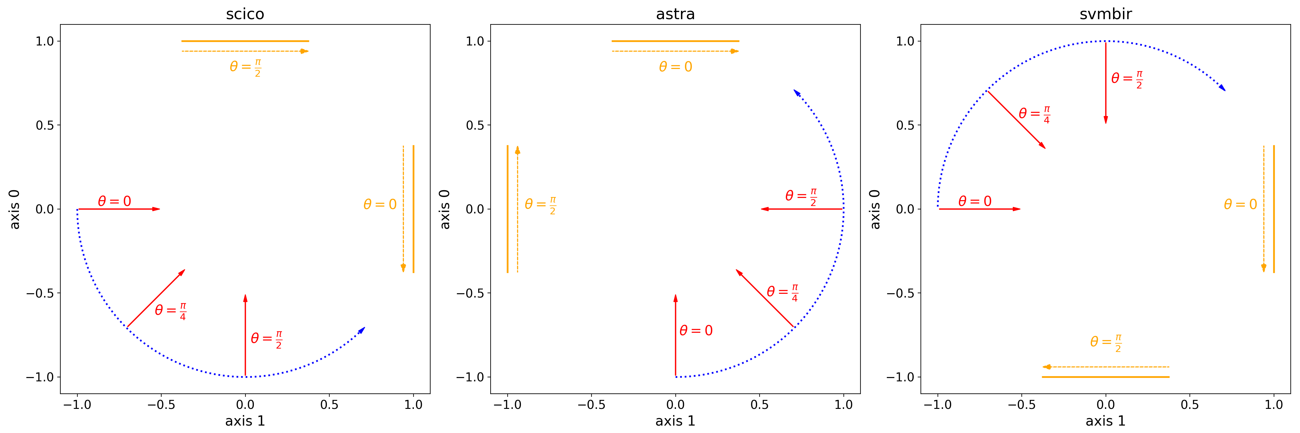
The SCICO, ASTRA, and svmbir transforms use different conventions for view angle directions, as illustrated in the figure below.

Comparison of 2D X-ray projector geometries. The radial arrows are directed towards the locations of the corresponding detectors, with the direction of increasing pixel indices indicated by the arrows on the dotted lines parallel to the detectors.
The conversion from the SCICO projection angle convention to those of the other two transforms is
3D Transforms
There are more significant differences in the interfaces for the 3D SCICO
and ASTRA transforms. The SCICO 3D transform xray.XRayTransform3D
defines the projection geometry in terms of a set of projection matrices,
while the geometry for the ASTRA 3D transform
astra.XRayTransform3D may either be specified in terms of a set
of view angles, or via a more general set of vectors specifying projection
direction and detector orientation. A number of support functions are
provided for convering between these conventions.
Note that the SCICO transform is implemented in JAX and can be run on both CPU and GPU devices, while the ASTRA transform is implemented in CUDA, and can only be run on GPU devices.
Modules
Abel transform LinearOperator wrapping the pyabel package. |
|
X-ray transform LinearOperators wrapping the ASTRA toolbox. |
|
X-ray transform LinearOperator wrapping the svmbir package. |
|
Cone beam X-ray transform for cylindrically symmetric objects. |
Functions
|
Translate an image to center the centroid. |
|
Estimate an image alignment rotation. |
|
Compute the centroid of an image. |
|
Rotate a 3D array. |
|
Estimate a volume alignment rotation. |
Classes
|
Parallel ray, single axis, 2D X-ray projector. |
|
General-purpose, 3D, parallel ray X-ray projector. |
- scico.linop.xray.center_image(v, axes=None, method=ResizeMethod.LANCZOS3)
Translate an image to center the centroid.
Translate an image (or higher-dimensional array) so that the centroid is at the spatial center of the image grid.
- Parameters:
- Return type:
- Returns:
Centered array.
- scico.linop.xray.image_alignment_rotation(img, max_angle=2.5, angle_step=0.025, center_factor=0.005)
Estimate an image alignment rotation.
Estimate the rotation that best aligns vertical straight lines in the image with the vertical axis.
The approach is roughly based on that used in the
find_img_rotation_2Dfunction in the cSAXS base package released by the CXS group at the Paul Scherrer Institute, which finds the rotation angle that results in the sparsest column sum according to the sparsity measure proposed in Sec 3.1 of [30]. (Note that an \(\ell_1\) norm sparsity measure is not suitable for this purpose since it is, in typical cases, appropximately invariant to the rotation angle.) The implementation here uses the plain ratio of \(\ell_1\) and \(\ell_2\) norms as a sparsity measure, more efficiently computes the column sums at different angles by exploiting the 2D X-ray transform, and includes a small bias for smaller angle rotations that improves performance when a range of rotation angles have the same sparsity measure.- Parameters:
img (
Union[Array,ndarray,bool,number,bool,int,float,complex]) – Array of pixel values.max_angle (
float) – Maximum angle (negative and positive) to test, in degrees.angle_step (
float) – Increment in angle values for range of angles to test, in degrees.center_factor (
float) – The angle multiplied by this scalar is added to the sparsity measure to slightly prefer smaller-angle solutions.
- Return type:
- Returns:
Rotation angle (in degrees) providing best alignment with the vertical (0) axis.
Notes
The number number of detector pixels for the 2D X-ray transform is chosen based on the shape \((N_0, N_1)\) of
imgand the value \(\theta\) of parametermax_angle, as indicated in Fig. 1.
Fig 1. Calculation of the number of detector pixels for the 2D X-ray transform.
- scico.linop.xray.image_centroid(v, center_offset=False)
Compute the centroid of an image.
Compute the centroid of an image or higher-dimensional array.
- Parameters:
- Return type:
- Returns:
Tuple of centroid coordinates.
- scico.linop.xray.rotate_volume(vol, rot, x=None, y=None, z=None, center=None)
Rotate a 3D array.
Rotate a 3D array as specified by an instance of
Rotation. Any axis coordinates that are not specified default to a range corresponding to the size of the array on that axis, starting at zero.- Parameters:
vol (
Union[Array,ndarray,bool,number,bool,int,float,complex]) – Array to be rotated.rot (
Rotation) – Rotation specification.x (
Union[Array,ndarray,bool,number,bool,int,float,complex,None]) – Coordinates forxaxis (axis 0).y (
Union[Array,ndarray,bool,number,bool,int,float,complex,None]) – Coordinates foryaxis (axis 1).z (
Union[Array,ndarray,bool,number,bool,int,float,complex,None]) – Coordinates forzaxis (axis 2).center (
Union[Array,ndarray,bool,number,bool,int,float,complex,None]) – A 3-vector specifying the center of rotation. Defaults to the center of the array.
- Return type:
- Returns:
Rotated array.
- scico.linop.xray.volume_alignment_rotation(vol, xslice=None, yslice=None, max_angle=2.5, angle_step=0.025, center_factor=0.005)
Estimate a volume alignment rotation.
Estimate the 3D rotation that best aligns planar structures in a volume with the x-y (0-1) plane. The algorithm is based on independent rotation angle estimates, obtained using
image_alignment_rotation, within 2D slices in the x-z (0-2) and y-z (1-2) planes. These estimates are integrated into a combined 3D rotation specification as explained in the technical note below.- Parameters:
vol (
Union[Array,ndarray,bool,number,bool,int,float,complex]) – Array of voxel values.max_angle (
float) – Maximum angle (negative and positive) to test, in degrees.angle_step (
float) – Increment in angle values for range of angles to test, in degrees.center_factor (
float) – The angle multiplied by this scalar is added to the sparsity measure to slightly prefer smaller-angle solutions.
- Return type:
- Returns:
Rotation object.
Notes
The estimation of the 3D rotation required to align planar structure in the volume with the x-y (0-1) plane is approached by estimating the 3D normal vector to this structure, illustrated in Fig. 1. The independent rotation angle estimates with the x-z (0-2) and y-z (1-2) planes are exploited as estimates (after a 90° rotation of each) as estimates of the projections of this normal vector into the x-z (0-2) and y-z (1-2) planes, illustrated in Figs. 2 and 3 respectively.

Fig 1. 3D orientation of the normal to the plane that is desired to be aligned with the x-y plane.

Fig 2. Projection of the normal onto the x-z plane.

Fig 3. Projection of the normal onto the y-z plane.
It can be observed from these figures that
\[\begin{split}x &= r_x \cos (\theta_x) \\ y &= r_y \cos (\theta_y) \\ z &= r_x \sin (\theta_x) = r_y \sin (\theta_y) \;,\end{split}\]where \((x, y, z)\) are the coordinates of the normal vector. We can write
\[r_x = \frac{z}{\sin(\theta_x)} \quad \text{and} \quad r_y = \frac{z}{\sin(\theta_y)} \;,\]and therefore
\[x = z \cot (\theta_x) \quad \text{and} \quad y = z \cot (\theta_y) \;.\]Since \((x, y, z) = z (\cot (\theta_x), \cot (\theta_y), 1)\) it is clear that the choice of \(z\) only affects the norm of the vector, and can therefore be set to unity. The rotation of this vector is then determined by computing the rotation required to align it (after normalization) with the \(z\) axis \((0, 0, 1)\).
- class scico.linop.xray.XRayTransform2D(input_shape, angles, x0=None, dx=None, y0=None, det_count=None, input_device=None, output_device=None)
Bases:
LinearOperatorParallel ray, single axis, 2D X-ray projector.
This implementation approximates the projection of each rectangular pixel as a boxcar function (whereas the exact projection is a trapezoid). Detector pixels are modeled as bins (rather than points) and this approximation allows fast calculation of the contribution of each pixel to each bin because the integral of the boxcar is simple.
By requiring the width of a projected pixel to be less than or equal to the bin width (which is defined to be 1.0), we ensure that each pixel contributes to at most two bins, which accelerates the accumulation of pixel values into bins (equivalently, makes the linear operator sparse).
Warning: The default pixel spacing is \(\sqrt{2}/2\) (rather than 1) in order to satisfy the aforementioned spacing requirement.
x0, dx, and y0 should be expressed in units such that the detector spacing dy is 1.0.
- Parameters:
angles (
Union[Array,ndarray,bool,number,bool,int,float,complex]) – (num_angles,) array of angles in radians. Viewing an (M, N) array as a matrix with M rows and N columns, an angle of 0 corresponds to summing rows, an angle of pi/2 corresponds to summing columns, and an angle of pi/4 corresponds to summing along antidiagonals.x0 (
Union[Array,ndarray,bool,number,bool,int,float,complex,None]) – (x, y) position of the corner of the pixel im[0,0]. By default, (-input_shape * dx[0] / 2, -input_shape * dx[1] / 2).dx (
Union[Array,ndarray,bool,number,bool,int,float,complex,None]) – Image pixel side length in x- and y-direction (axis 0 and 1 respectively). Must be set so that the width of a projected pixel is never larger than 1.0. By default, [\(\sqrt{2}/2\), \(\sqrt{2}/2\)].y0 (
Optional[float]) – Location of the edge of the first detector bin. By default, -det_count / 2det_count (
Optional[int]) – Number of elements in detector. IfNone, defaults to the size of the diagonal of input_shape.input_device (
Device|Sharding|None) – (optional)DeviceorShardingfor input arrays.output_device (
Device|Sharding|None) – (optional)DeviceorShardingfor output arrays.
- fbp(y)[source]
Compute filtered back projection (FBP) inverse of projection.
Compute the filtered back projection inverse by filtering each row of the sinogram with the filter defined in (61) in [33] and then back projecting. The projection angles are assumed to be evenly spaced in \([0, \pi)\); reconstruction quality may be poor if this assumption is violated. Poor quality reconstructions should also be expected when dx[0] and dx[1] are not equal.
- class scico.linop.xray.XRayTransform3D(input_shape, matrices, det_shape, input_dtype=<class 'numpy.float32'>, input_device=None, output_device=None)
Bases:
LinearOperatorGeneral-purpose, 3D, parallel ray X-ray projector.
This projector approximates cubic voxels projecting onto rectangular pixels and provides a back projector that is the exact adjoint of the forward projector. It is written purely in JAX, allowing it to run on either CPU or GPU and minimizing host copies.
Warning: This class is experimental and may be up to ten times slower than
scico.linop.xray.astra.XRayTransform3D.For each view, the projection geometry is specified by an array with shape (2, 4) that specifies a \(2 \times 3\) projection matrix and a \(2 \times 1\) offset vector. Denoting the matrix by \(\mathbf{M}\) and the offset by \(\mathbf{t}\), a voxel at array index (i, j, k) has its center projected to the detector coordinates
\[\begin{split}\mathbf{M} \begin{bmatrix} i + \frac{1}{2} \\ j + \frac{1}{2} \\ k + \frac{1}{2} \end{bmatrix} + \mathbf{t} \,.\end{split}\]The detector pixel at index (i, j) covers detector coordinates \([i+1) \times [j+1)\).
XRayTransform3D.matrices_from_euler_anglescan help to make these geometry arrays.- Parameters:
matrices (
Union[Array,ndarray,bool,number,bool,int,float,complex]) – (num_views, 2, 4) array of homogeneous projection matrices.input_dtype (
DType) – Input array dtype.input_device (
Device|Sharding|None) – (optional)DeviceorShardingfor input arrays.output_device (
Device|Sharding|None) – (optional)DeviceorShardingfor output arrays.
- static matrices_from_euler_angles(input_shape, output_shape, seq, angles, degrees=False, voxel_spacing=None, det_spacing=None)[source]
Create a set of projection matrices from Euler angles. The input voxels will undergo the specified rotation and then be projected onto the global xy-plane.
- Parameters:
output_shape (
Tuple[int,...]) – Shape of output (detector).str – Sequence of axes for rotation. Up to 3 characters belonging to the set {‘X’, ‘Y’, ‘Z’} for intrinsic rotations, or {‘x’, ‘y’, ‘z’} for extrinsic rotations. Extrinsic and intrinsic rotations cannot be mixed in one function call.
angles (
Union[Array,ndarray,bool,number,bool,int,float,complex]) – (num_views, N), N = 1, 2, or 3 Euler angles.degrees (
bool) – IfTrue, angles are in degrees, otherwise radians. Default:True, radians.voxel_spacing (
Union[Array,ndarray,bool,number,bool,int,float,complex]) – (3,) array giving the spacing of image voxels. Default: [1.0, 1.0, 1.0]. Experimental.det_spacing (
Union[Array,ndarray,bool,number,bool,int,float,complex]) – (2,) array giving the spacing of detector pixels. Default: [1.0, 1.0]. Experimental.
- Return type:
- Returns:
(num_views, 2, 4) array of homogeneous projection matrices.