scico.linop.xray.astra
X-ray transform LinearOperators wrapping the ASTRA toolbox.
X-ray transform LinearOperator wrapping the parallel beam
projections in the
ASTRA toolbox.
This package provides both C and CUDA implementations of core
functionality, but note that use of the CUDA/GPU implementation is
expected to result in GPU-host-GPU memory copies when transferring
JAX arrays. Other JAX features such as automatic differentiation are
not available.
Functions here refer to three coordinate systems: world coordinates, volume coordinates, and detector coordinates. World coordinates are 3D coordinates representing a point in physical space. Volume coordinates refer to a position in the reconstruction volume, where the voxel with its intensity value stored at vol[i, j, k] has its center at volume coordinate (i+0.5, j+0.5, k+0.5) and side lengths of 1. Detector coordinates refer to a position on the detector array, and the pixel at det[i, j] has its center at detector coordinates (i+0.5, j+0.5) and side lengths of one.
Functions
|
Convert det_spacing and angles to vector geometry specification. |
|
Convert SCICO projection matrices into ASTRA "parallel3d_vec" vectors. |
|
Convert X-ray geometry specification to a SCICO projection matrix. |
|
Project world coordinates along ray into the specified basis. |
|
Rotate geometry specification vectors. |
|
Set the index/indices of GPU(s) to be used by astra. |
|
Convert a volume coordinate into a world coordinate. |
Classes
|
2D parallel beam X-ray transform based on the ASTRA toolbox. |
|
3D parallel beam X-ray transform based on the ASTRA toolbox. |
- scico.linop.xray.astra.set_astra_gpu_index(idx)[source]
Set the index/indices of GPU(s) to be used by astra.
- scico.linop.xray.astra.project_world_coordinates(x, ray, d, u, v, det_shape)[source]
Project world coordinates along ray into the specified basis.
Project world coordinates along ray into the basis described by u and v with center d.
- Parameters:
x (
ndarray) – (…, 3) vector(s) of world coordinates.ray (
TypeAliasType) – (3,) ray directiond (
TypeAliasType) – (3,) center of the detectoru (
TypeAliasType) – (3,) vector from detector pixel (0,0) to (0,1), columns, xv (
TypeAliasType) – (3,) vector from detector pixel (0,0) to (1,0), rows, y
- Return type:
- Returns:
(…, 2) vector(s) in the detector coordinates
- scico.linop.xray.astra.volume_coords_to_world_coords(idx, vol_geom)[source]
Convert a volume coordinate into a world coordinate.
Convert a volume coordinate into a world coordinate using ASTRA conventions.
- class scico.linop.xray.astra.XRayTransform2D(input_shape, det_count, det_spacing, angles, det_offset=0.0, volume_geometry=None, device='auto')[source]
Bases:
LinearOperator2D parallel beam X-ray transform based on the ASTRA toolbox.
Perform tomographic projection (also called X-ray projection) of an image at specified angles, using the ASTRA toolbox.
- Parameters:
det_count (
int) – Number of detector elements in the projection geometry.det_spacing (
float) – Spacing between detector elements in the projection geometry.angles (
ndarray) – Array of projection angles in radians.det_offset (
float) – Offset of the detector center. Negative/positive values correspond to left/right detector shifts (i.e. right/left shifts of the projection within the image) respectively. Note thatfbpcannot be used when this offset is non-zero.volume_geometry (
Optional[List[float]]) – Specification of the shape of the discretized reconstruction volume. Must either beNone, in which case it is inferred from input_shape, or be a list ofintorfloatscalars corresponding to the valid parameters ofastra.creators.create_vol_geom.device (
str) – Specifies device for projection operation. One of [“auto”, “gpu”, “cpu”]. If “auto”, a GPU is used if available, otherwise, the CPU is used.
- fbp(sino, filter_type='Ram-Lak')[source]
Filtered back projection (FBP) reconstruction.
Perform tomographic reconstruction using the filtered back projection (FBP) algorithm.
- Parameters:
sino (
Array) – Sinogram to reconstruct.filter_type (
str) – Select the filter to use. For a list of options seecfg.FilterTypein the ASTRA documentation.
- Return type:
- Returns:
Reconstructed volume.
- scico.linop.xray.astra.convert_from_scico_geometry(in_shape, matrices, det_shape)[source]
Convert SCICO projection matrices into ASTRA “parallel3d_vec” vectors.
For 3D arrays, in ASTRA, the dimensions go (slices, rows, columns) and (z, y, x); in SCICO, the dimensions go (x, y, z).
In ASTRA, the x-grid (recon) is centered on the origin and the y-grid (projection) can move. In SCICO, the x-grid origin is the center of x[0, 0, 0], the y-grid origin is the center of y[0, 0].
See section “parallel3d_vec” in the astra documentation.
- Parameters:
- Return type:
- Returns:
(num_angles, 12) vector array in the ASTRA “parallel3d_vec” convention.
- scico.linop.xray.astra.convert_to_scico_geometry(input_shape, det_count, det_spacing=None, angles=None, vectors=None)[source]
Convert X-ray geometry specification to a SCICO projection matrix.
The approach is to locate 3 points in the volume domain, deduce the corresponding projection locations, and, then, solve a linear system to determine the affine relationship between them.
- Parameters:
det_count (
Tuple[int,int]) – Number of detector elements. See the astra documentation for more information.det_spacing (
Optional[Tuple[float,float]]) – Spacing between detector elements. See the astra documentation for more information.angles (
Optional[ndarray]) – Array of projection angles in radians. This parameter is mutually exclusive with vectors.vectors (
Optional[ndarray]) – Array of ASTRA geometry specification vectors. This parameter is mutually exclusive with angles.
- Return type:
- Returns:
(num_angles, 2, 4) array of homogeneous projection matrices.
- class scico.linop.xray.astra.XRayTransform3D(input_shape, det_count, det_spacing=None, det_offset=None, angles=None, vectors=None)[source]
Bases:
LinearOperator3D parallel beam X-ray transform based on the ASTRA toolbox.
Perform tomographic projection (also called X-ray projection) of a volume at specified angles, using the ASTRA toolbox. The 3D geometries “parallel3d” and “parallel3d_vec” are supported by this interface. Note that a CUDA GPU is required for the primary functionality of this class; if no GPU is available, initialization will fail with a
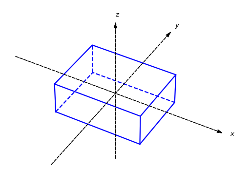
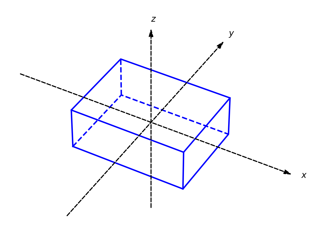
RuntimeError.The volume is fixed with respect to the coordinate system, centered at the origin, as illustrated below:
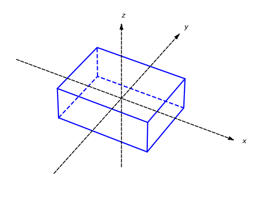
The voxels sides have unit length (in arbitrary units), which defines the scale for all other dimensions in the source-volume-detector configuration. Geometry axes z, y, and x correspond to volume array axes 0, 1, and 2 respectively. The projected array axes 0, 1, and 2 correspond respectively to detector rows, views, and detector columns.
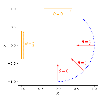
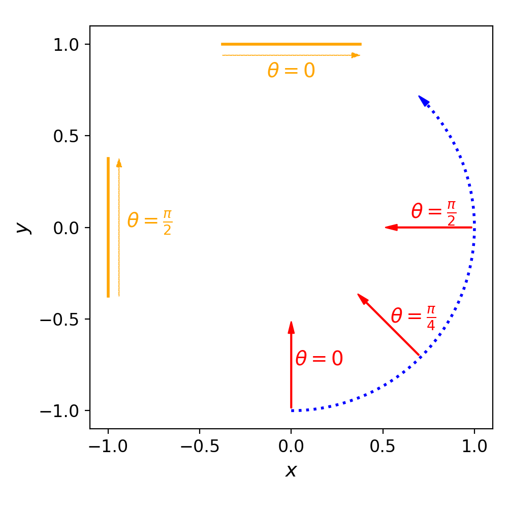
In the “parallel3d” case, the source and detector rotate clockwise about the z axis in the x-y plane, as illustrated below:
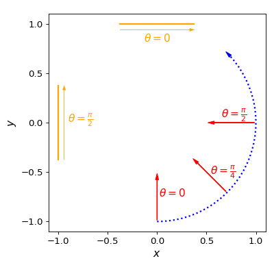
Each radial arrow indicates the direction of the beam towards the detector (indicated in orange in the “light” display mode) and the arrow parallel to the detector indicates the direction of increasing pixel indices.
In this case the z axis is in the same direction as the vertical/row axis of the detector and its projection corresponds to a vertical line in the center of the horizontal/column detector axis. Note that the view images must be displayed with the origin at the bottom left (i.e. vertically inverted from the top left origin image indexing convention) in order for the projections to correspond to the positive up/negative down orientation of the z axis in the figures here.
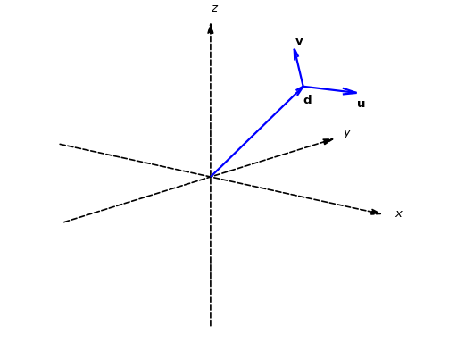
In the “parallel3d_vec” case, each view is determined by the following vectors:
View definition vectors¶ \(\mb{r}\)
Direction of the parallel beam
\(\mb{d}\)
Center of the detector
\(\mb{u}\)
Vector from detector pixel (0,0) to (0,1) (direction of increasing detector column index)
\(\mb{v}\)
Vector from detector pixel (0,0) to (1,0) (direction of increasing detector row index)
Note that the components of these vectors are in x, y, z order, not the z, y, x order of the volume axes.
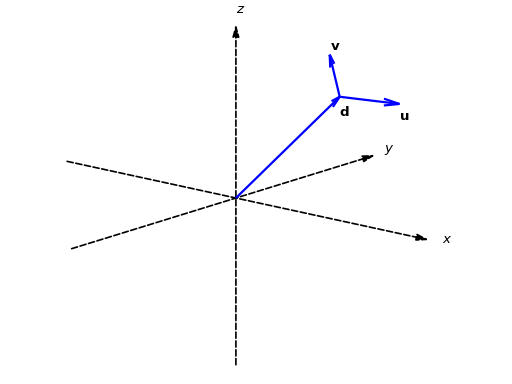
Vector \(\mb{r}\) is not illustrated to avoid cluttering the figure, but will typically be directed toward the center of the detector (i.e. in the direction of \(\mb{d}\) in the figure.) Since the volume-detector distance does not have a geometric effect for a parallel-beam configuration, \(\mb{d}\) may be set to the zero vector when the detector and beam centers coincide (e.g., as in the case of the “parallel3d” geometry). Note that the view images must be displayed with the origin at the bottom left (i.e. vertically inverted from the top left origin image indexing convention) in order for the row indexing of the projections to correspond to the direction of \(\mb{v}\) in the figure.
These vectors are concatenated into a single row vector \((\mb{r}, \mb{d}, \mb{u}, \mb{v})\) to form the full geometry specification for a single view, and multiple such row vectors are stacked to specify the geometry for a set of views.
Keyword arguments det_spacing and angles should be specified to use the “parallel3d” geometry, and keyword argument vectors should be specified to use the “parallel3d_vec” geometry. These parameters are mutually exclusive.
- Parameters:
det_count (
Tuple[int,int]) – Number of detector elements in the projection geometry.det_spacing (
Optional[Tuple[float,float]]) – Spacing between detector elements in the projection geometry.det_offset (
Optional[Tuple[float,float]]) – Offset of the the detector center as a tuple (horizontal shift, vertical shift). Negative/positive values correspond to left/right and up/down detector shifts (i.e. right/left and down/up shifts of the projection within the image) respectively.angles (
Optional[ndarray]) – Array of projection angles in radians. This parameter is mutually exclusive with vectors.vectors (
Optional[ndarray]) – Array of ASTRA geometry specification vectors. This parameter is mutually exclusive with angles.
- Raises:
RuntimeError – If a CUDA GPU is not available to the ASTRA toolbox.
- static create_astra_geometry(input_shape, det_count, det_spacing=None, angles=None, vectors=None)[source]
Create ASTRA 3D geometry objects.
Keyword arguments det_spacing and angles should be specified to use the “parallel3d” geometry, and keyword argument vectors should be specified to use the “parallel3d_vec” geometry. These parameters are mutually exclusive.
- Parameters:
det_count (
Tuple[int,int]) – Number of detector elements in the projection geometry.det_spacing (
Optional[Tuple[float,float]]) – Spacing between detector elements in the projection geometry.angles (
Optional[ndarray]) – Array of projection angles in radians.vectors (
Optional[ndarray]) – Array of geometry specification vectors.
- Return type:
- Returns:
A tuple (vol_geom, proj_geom) of ASTRA volume geometry and projection geometry objects.
- scico.linop.xray.astra.angle_to_vector(det_spacing, angles)[source]
Convert det_spacing and angles to vector geometry specification.